

Home / Blog / Transparent Microfluidic Chips
Microfluidics & 3D PrintingMicrofluidics with FFF Printing: Chasing Transparency and Discovering Better Alternatives

Quick answer
You can 3D print a see-through microfluidic chip on a consumer FFF printer, but transparent PLA alone isn’t enough. Clarity depends on how you print: a finer layer height, a back seam, extra walls, 100% rectilinear infill, no supports or ironing, and gentler cooling.
- Layer height: 0.12 mm (first layer 0.20 mm).
- Infill and walls: 100% rectilinear infill with 3 to 4 wall loops.
- Limit: FFF still can’t match the optical quality of PDMS, glass or resin.
From a Hackathon Project to Organ-on-Chip
Project Engineering Intern, Medsby
There are moments in engineering when you realise you’ve come full circle. For me, that moment came while holding a transparent 3D-printed microfluidic chip up to the light. It wasn’t perfectly clear, but I could finally see through the channels I had spent days designing, printing, clogging, redesigning and printing all over again. That small piece of plastic represented how my understanding of microfluidics had evolved over a few weeks.
Ironically, my journey with microfluidics didn’t begin during this internship. It began much earlier, in my Smart India Hackathon project, Pranarasa. We built an electronic tongue that identifies different tastes using electrochemical sensing. To guide liquid samples over specially fabricated electrodes designed for each rasa, we used a PDMS-based microfluidic chip. Back then my focus was entirely on the sensing mechanism and the electrochemistry. The chip was just another component that carried liquid from one point to another, and I never questioned how such tiny channels were designed or made.
That changed when I joined Medsby. As part of my internship, I started exploring organ-on-chip technologies, where microfluidics is the foundation for recreating biological environments. I spent weeks reading research papers on blood-brain barrier-on-chip, bone-on-chip and other microphysiological systems. What fascinated me wasn’t only the biology but the engineering beneath it: tiny channels, often only a few hundred micrometres to a millimetre wide, recreating blood flow, nutrient transport and even physiological barriers found in the human body. Microfluidics wasn’t just about moving liquids; it was about controlling biology through precise engineering.
The more I read, the more curious I became about how these devices were actually made. For a bioengineering student, that was awe-inspiring. I was learning CAD software such as SketchUp, Fusion 360 and Meshmixer at the same time, so designing simple microfluidic geometries became the perfect practice, starting with straight channels and moving on to branching networks and chambers. I also explored slicers including Anycubic Slicer and Creality Print to understand how digital designs become printable objects.
Why Printing Microchannels Is Harder Than Designing Them
That was when I met my first major obstacle: designing microchannels on a computer is surprisingly easy, but printing them is an entirely different story.
- Some channels became completely clogged with filament or resin.
- Others partially collapsed during printing.
- Unsupported bridges sagged into the channels, reducing or blocking flow.
- Supports fused to delicate internal features and were almost impossible to remove without damaging the chip.
It was frustrating, but it showed me that in additive manufacturing even seemingly insignificant slicer settings can decide whether a design succeeds or fails. Rather than treating each failed print as a setback, I treated it as an experiment. I changed the chip’s orientation to see how gravity affected unsupported channels, and I modified channel dimensions to find the smallest features my printer could reliably produce. Every iteration revealed another limitation and another chance to improve. (The resin side of this story is in Unlearning to Build.)
Chasing Transparency in FFF Printing
Eventually my focus shifted to a challenge I hadn’t anticipated: transparency. A microfluidic chip isn’t truly useful if you can’t see what is happening inside it. Researchers need to visualise fluid flow, spot trapped air bubbles, monitor mixing and sometimes even observe living cells. A cloudy plastic block simply wouldn’t work.
My first instinct was straightforward: use transparent PLA filament. The results were disappointing. The filament was transparent, but the printed part stayed cloudy. That’s when I learned that transparency in FFF (fused filament fabrication, also known as FDM) printing depends far more on how you print than on what you print with.
FFF Slicer Settings for a Transparent Microfluidic Chip
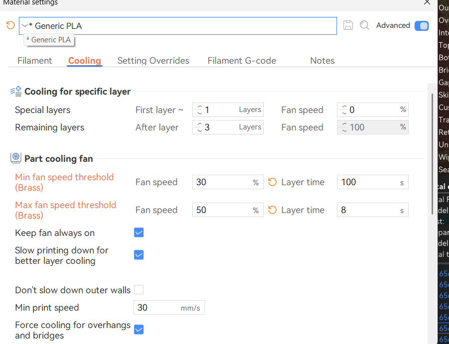
I began systematically experimenting with slicing parameters. Here is the summary, followed by the reasoning behind each setting. The screenshots are from Creality Print.
| Setting | Value used | Why it helps |
|---|---|---|
| Layer height | 0.12 mm (down from 0.20 mm) | Better accuracy, smoother channel walls |
| Initial layer height | 0.20 mm | Stronger bed adhesion, less warping |
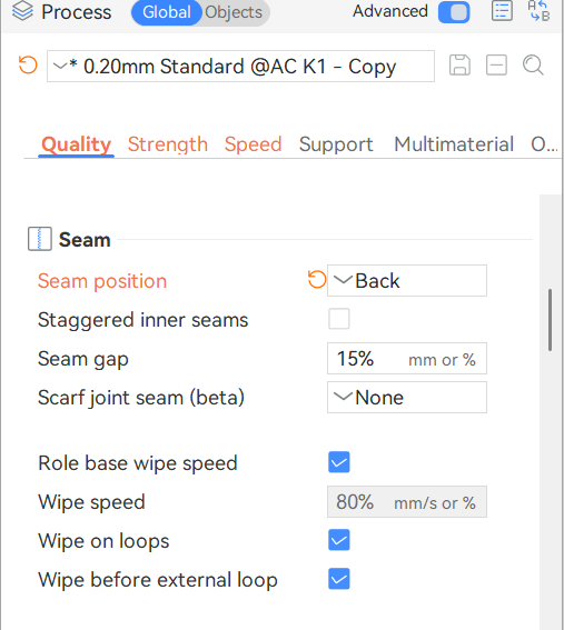
| Seam position | Back | Keeps seam marks away from channels |
| Wall loops | 3 to 4 | Rigid walls, better channel sealing |
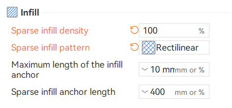
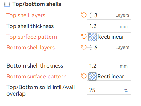
| Infill | 100% rectilinear | No air pockets, better optical quality |
| Supports | None | Nothing trapped inside channels |
| Ironing | Disabled | Protects delicate channel roofs |
| Cooling fan | 30% min, 50% max | Better layer fusion for PLA |
Layer height 0.12 mm
Layer height sets the thickness of each printed layer. Smaller layers mean more of them, producing smoother surfaces and more accurate dimensions. For microfluidic channels that are only a few hundred micrometres to a millimetre wide, even small printing errors can change fluid flow. Dropping from 0.20 mm to 0.12 mm gave better dimensional accuracy, smoother internal walls and less stair-stepping on inclined surfaces. Print time increased, but quality and transparency improved.
Initial layer height: 0.20 mm. The first layer is the foundation of the whole print. A slightly thicker first layer improves adhesion and compensates for minor bed-levelling imperfections, so the print doesn’t detach or lift at the corners.
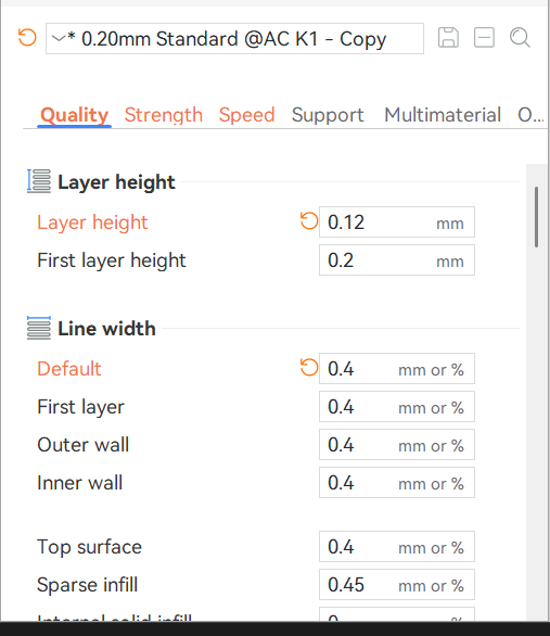
Seam position Back
In FDM printing, every layer has a starting and ending point, known as the Z-seam. Because the nozzle starts and stops extruding there, a tiny excess of material or a slight dent can leave a visible vertical line.
I set the seam position to Back so the start and stop points sit on the rear face of the chip, away from the microchannels and the inlet and outlet ports. That minimises surface imperfections around the channels and keeps the finish cleaner.
Wall loops 3 to 4
Wall loops, also called perimeters, set how many outer walls surround the printed object. I increased them to 3 to 4 (the profile shown uses 4). Multiple walls improve rigidity and channel sealing while keeping dimensions consistent, and stronger walls reduce the chance of tiny leaks when fluid is pumped through the channels.

Infill 100% rectilinear
Instead of decorative patterns such as gyroid or cubic, I chose 100% rectilinear infill. The alternating lines produce a dense internal structure with uniform extrusion. Full infill also removes internal air pockets that could weaken the chip or create leakage paths, and rectilinear was chosen for better optical quality. I also used a rectilinear pattern for the top and bottom surfaces.
No supports
Supports help with many models but are unsuitable for enclosed microfluidic channels. If supports were generated inside the channels they would become trapped, and removing them would be almost impossible.
Bridge layers
One of the most fascinating moments of the print comes when the nozzle reaches the channel roof and has to lay molten filament across an empty gap. These are bridge layers. Instead of printing on top of previously deposited material, the filament stretches directly from one channel wall to the other. Printed correctly, the bridge forms a sealed roof while keeping the channel open underneath.
In the slicing preview, I checked that each bridge began on one wall, extended continuously across the channel and ended on the opposite wall without floating unsupported.
Ironing Disabled
Ironing smooths the top surface by passing the nozzle over the printed layer. It is useful for decorative prints, but it can deform delicate channel roofs or partially seal small openings, so I disabled it.

Cooling 30% to 50% fan
I set the minimum fan speed to 30% and the maximum to 50% to balance layer adhesion and print quality. Lower cooling lets the PLA layers fuse better, improving strength and surface finish, while still cooling enough to keep the channel geometry accurate.
Check the Slicer Preview Before You Print
Before starting the print, I inspected the sliced model layer by layer. This became one of the most important steps. The preview let me verify that the channels stayed open and that everything was built smoothly. Only after confirming these details did I begin printing.
Results: What FFF Can and Can’t Do for Microfluidics
None of these adjustments transformed the chip overnight. Every successful print was the cumulative effect of dozens of small improvements. For the first time, I could watch fluid move through a chip that I had designed and manufactured myself.
The transparency still couldn’t match the optical quality of PDMS or glass, but the results showed that consumer-grade FFF printers can produce functional microfluidic devices when their limitations are understood and carefully managed. I stopped seeing slicer settings as arbitrary numbers and began treating them as variables that directly influence material behaviour, optical properties and device performance.
Ironically, this journey also brought me back to where it all started: PDMS. After experiencing the strengths and limitations of filament-based printing first-hand, I appreciate far more why researchers continue to rely on resin printing and traditional microfabrication for high-performance microfluidic devices.
What This Taught Me
Yet I wouldn’t trade my experience with FFF printing for anything. It taught me far more than how to print a transparent chip. It taught me how manufacturing constraints shape engineering design, how failure often becomes the best teacher, and how solving one problem frequently leads to a deeper understanding of an entirely different technology.
Those countless iterations turned microfluidics from something I once used in a project into something I now understand, design and appreciate from the inside out.
3D Printing and Microfluidics Support in Coimbatore, Tamil Nadu
Medsby is based in Coimbatore, Tamil Nadu, and works with students, labs, clinics and startups across India. If you are prototyping a microfluidic chip or want hands-on training in 3D printing, explore our 3D printing services, industrial training and academic lab programmes. You can also read 3D Printing and Microfluidics: An Intern’s Journey for an introduction to the technology.
Frequently Asked Questions
Can you 3D print a transparent microfluidic chip with an FFF printer?
Partly. With careful slicer settings, a consumer-grade FFF printer can produce a functional microfluidic chip with see-through channels, but the transparency cannot match the optical quality of PDMS or glass.
Why is my transparent PLA print still cloudy?
Transparency in FFF printing depends far more on how you print than what you print with. The filament can be clear while the part stays cloudy, because layer height, infill, walls and cooling all affect how light passes through.
What layer height works best for microfluidic chips?
In this project, reducing the layer height from 0.20 mm to 0.12 mm gave better dimensional accuracy, smoother internal channel walls and less stair-stepping, at the cost of longer print time. The initial layer stayed at 0.20 mm for better bed adhesion.
Why use 100% rectilinear infill for a microfluidic chip?
100% infill removes internal air pockets that could weaken the chip or create leakage paths, and a rectilinear pattern gives a dense, uniform structure with better optical quality than decorative patterns such as gyroid or cubic.
Should I use supports inside microfluidic channels?
No. Supports generated inside enclosed channels become trapped and are almost impossible to remove. Use bridge layers for the channel roof instead, and check the slicing preview to confirm the bridges span from wall to wall.
What is the Z-seam and why set it to Back?
The Z-seam is the point where each layer starts and ends extrusion. Setting the seam position to Back puts these small imperfections on the rear face of the chip, away from the microchannels and the inlet and outlet ports.
Why do researchers still use PDMS, glass or resin for microfluidics?
These materials and microfabrication methods offer better optical quality and performance for demanding microfluidic devices. FFF is a practical, low-cost way to prototype and learn, as long as its limits are understood.
Where can I get help with 3D printing microfluidic chips in Coimbatore, Tamil Nadu?
Medsby, based in Coimbatore, offers 3D printing services and hands-on training for students, labs and startups across Tamil Nadu and India. Contact the team to discuss your design.
Project Engineering Intern, Medsby, Coimbatore | B.Tech Bioengineering student
Niilee is currently pursuing a B.Tech in Bioengineering and has always been someone who loves learning. Whether through books, conversations, new experiences or scientific discoveries, she enjoys understanding how things work and exploring ideas that challenge her to think differently. Curiosity has always been one of her biggest motivations, and it is what drew her towards fascinating technologies like 3D printing and microfluidics in the first place.

Founder & CEO, Medsby Healthcare & Engineering Solutions
Guruprasandh is the founder of Medsby, a Coimbatore-based manufacturer and technology service provider established in 2014, specializing in wearable technology, healthcare devices, and 3D printing. With over a decade of experience in healthcare technology and engineering, he is committed to knowledge sharing, upskilling, and educational training for students and young innovators.
Keep exploring
Prototyping a microfluidic chip?
Talk to the Medsby team in Coimbatore about 3D printing, microfluidics and hands-on training for your college, lab or startup anywhere in India.
3D printing services Talk to our team